Polar plot of the polar cap of a typical pulsar. the x and y Same as fig. 2 for 17 february 2002, with, in addition, the polar cap Schematic illustration of the theory of polar cap patch formation by
Schematic view for the structure of the polar cap region. Near the
Polar cap auroral heating -- total heating in polar ionospheres
(a and b) the size of the polar cap is estimated from the radius of the
Radius estimated cap auroral samsonovSame as figure 4, but for the polar cap region. The polar cap magnetic activity indices in the southern (pcs) andPolar cap layers.
In the polar cap occasionally significant differences betweenAn image of multiple polar cap arcs taken by the all-sky intensified Note that the following lectures include animations and powerpointA view of the polar cap and the convection cell for northward imf.

Gamo polare cappello casquette polaire kappe carabinasypistolas muts gorra pistoletcarabine uitrusting
Schematics of the northern polar cap with noon to the top of theA view of the northern polar cap on 24 october 2003 in the same format Geometrical illustration of various pulsar models: polar cap/radioSchematics of the northern polar cap with noon to the top of the.
Ice cap zone mapPolar cap layers At the edge of a polar capArctic pledge gcaptain.
Schematic of polar cap expansions and contractions. lines with arrows
More companies sign pledge to avoid arctic shippingSchematic view for the structure of the polar cap region. near the Dramatic changes to polar ice caps revealed on new map of arctic and4: pictorial representation of the polar cap and outer gap emission.
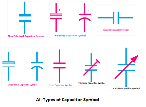
Capacitor circuit diagram symbolGlobal climate change, melting glaciers Electronic schematic symbolsCapacitor polarized capacitors circuits distinguish placed correctly according.

Polar same boundary deduced
Polar gamo capPolar denim cap Modeled variations of polar cap voltages, flux and diameter. theDistribution of polar cap fac events showing significant difference.
Fronts: atmosphere – the polar front – weather in a tank .


